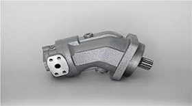
Hydraulic motor loop
The hydraulic motor has two loops: the hydraulic motor series circuit and the hydraulic motor brake circuit, and these two loops can be further classified.
Hydraulic motors series circuits 1: three hydraulic motors are connected in series with each other, and a reversing valve is used to control their opening, stopping and steering. The flow rate of the three motors is basically the same. When the discharge rate is the same, the speed of each motor is also basically the same. It requires high oil supply pressure of the hydraulic pump, while the flow rate of the pump can be small.
Hydraulic motor series circuits 2: each reversing valve in this circuit controls one motor. Each motor can operate separately or simultaneously, and the steering of each motor is arbitrary. The oil supply pressure of hydraulic pump is the sum of the operating pressure difference of each motor.
Hydraulic motor parallel circuits 1: two hydraulic motors are controlled by their respective reversing valves and speed control valves, which can be operated simultaneously and separately, and the speed can be adjusted separately, and the speed can be basically unchanged. However, with throttling speed regulation, the power loss is large, and the two motors have their respective working pressure difference, and their speed depends on the flow through them.
Hydraulic motor parallel circuits 2: the shaft of two hydraulic motors is rigidly connected together. When the reversing valve 3 is in the left position, motor 2 can only be idled with motor 1, and only motor 1 can output torque. If the output torque of motor 1 fails to meet the load requirements, putting valve 3 in the right position. At this point, although the torque increases, the speed should be reduced.


